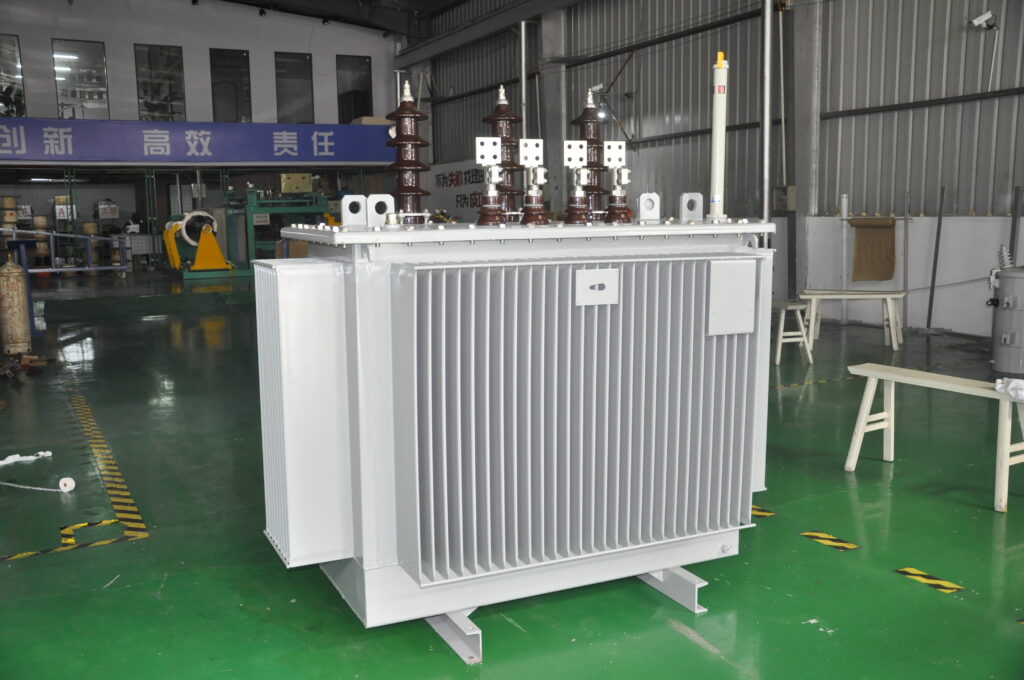
Regular insulation resistance testing of transformers is essential to ensure operational safety, extend equipment lifespan, and prevent electrical faults. This process, often conducted with a megohmmeter (also known as a “megger”), allows operators to measure insulation quality and detect potential leakage currents that may compromise transformer performance. Below, we discuss key considerations when performing insulation testing on transformers.
1. Pre-Test Preparation: Cleaning and Disconnecting Ground Lines
Before insulation testing begins, it’s important to clean the insulator bushings thoroughly. Dust, moisture, or other contaminants can lead to inaccurate resistance readings by creating unintended conductive paths along the surface of the bushings. Additionally, disconnect all grounding lines and isolate the neutral line to prevent any interference that may alter the test results. Ensuring these connections are removed helps create a stable testing environment and avoids safety hazards that could arise from grounding.
2. Choosing the Right Megohmmeter and Recording Oil Temperature
Selecting a suitable megohmmeter is crucial for obtaining accurate results. Different transformers require megohmmeters of varying voltage capacities, so consult the manufacturer’s specifications for guidance. Recording the transformer oil temperature at the time of testing is equally important, as insulation resistance varies with temperature. A higher oil temperature usually results in lower resistance readings, so capturing this data allows for proper interpretation and adjustment of results, particularly if comparing them with previous readings under different conditions.
3. Safety Precautions: Avoiding Direct Contact and Discharging the Winding
During testing, avoid direct contact with any live conductors to prevent electrical shock. Insulation resistance testing involves high voltage, so touching the transformer while the test is in progress poses serious risks. After completing the test, discharge the windings by grounding them for a few moments to safely release any residual charge. This step is essential for safety, as the winding can retain a charge after testing, potentially endangering operators and other equipment nearby.
4. Testing Parameters: Dual-Winding Transformer Measurements
For dual-winding transformers, testing should cover:
- Primary to Secondary insulation resistance
- Primary to Ground insulation resistance
- Secondary to Primary insulation resistance
- Secondary to Ground insulation resistance
These measurements provide a comprehensive view of the transformer’s insulation integrity. Testing both windings against each other and to the ground helps identify faults within each circuit segment and assures that insulation between the primary and secondary circuits is sufficient to prevent unwanted electrical coupling or arcing.
Why Insulation Testing Matters for Transformer Health
Regular insulation resistance testing provides multiple benefits:
- Early Fault Detection: Insulation deterioration often progresses slowly, but regular testing allows for early detection, reducing the likelihood of sudden transformer failures.
- Improved Safety: High-voltage transformers carry inherent risks, and routine testing mitigates hazards by ensuring insulation can withstand operational voltages.
- Cost Savings: By catching issues early, operators can perform targeted maintenance, avoiding costly repairs or replacements.
Conclusion
In summary, correct transformer insulation testing requires careful preparation, safety measures, and detailed measurements across multiple points within the transformer’s circuits. These tests, when performed regularly, contribute to both transformer reliability and operator safety. By following best practices and adhering to the correct testing sequence, operators can confidently assess insulation health and optimize maintenance schedules, ensuring the longevity and dependability of transformers in power systems.
